
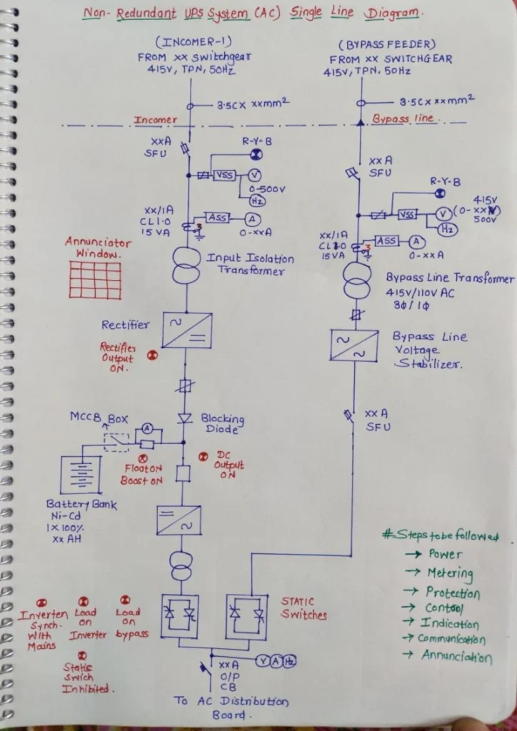
In the world of electrical engineering, uninterruptible power supply (UPS) systems play a crucial role in ensuring the continuous operation of critical equipment. Today, we’ll be delving deep into a non – redundant AC UPS system, exploring its components, operation, and significance through a detailed single – line diagram.
1. Major Components & Their Role for AC UPS Systems
1.1 AC Incomer (Normal Supply)
The AC incomer is the lifeline of the UPS system during normal operation. It draws power from a 415V, 3 – Phase, TPN (Three – Phase, Neutral, and Protective Earth), 50 Hz source in the low – voltage switchgear. This primary power supply is protected by SFU (Safety Fuse Unit) or MCCB (Molded Case Circuit Breaker) to safeguard against short – circuits and overloads. The 3.5C cables ensure the continuity of the phase and neutral connections. Without a stable AC incomer, the UPS system would not have the initial power to function under normal conditions.
1.2 Input Isolation Transformer
The input isolation transformer acts as a shield between the grid and the UPS system. It provides galvanic isolation, which is essential for reducing harmonics, noise, and ground loops. By minimizing these electrical disturbances, it significantly enhances the reliability and safety of the entire UPS setup. For example, in industrial environments where there are high levels of electrical noise, this transformer helps to ensure that the UPS and the connected critical loads receive clean power.
1.3 Rectifier
The rectifier is a key component that converts alternating current (AC) from the AC incomer into direct current (DC). This DC power is then used to feed the DC bus and charge the battery bank in either float or boost mode. In float mode, the battery is maintained at a constant state of charge, while in boost mode, the battery is rapidly charged when needed. The rectifier’s ability to provide a stable DC supply is fundamental for the subsequent operation of the UPS.
1.4 Battery Bank (Ni – Cd / VRLA)
The battery bank, whether it’s a Nickel – Cadmium (Ni – Cd) or Valve – Regulated Lead – Acid (VRLA) type, is the backup power source for the UPS. Connected via an MCCB, it comes into action during a mains failure. The blocking diode in the circuit prevents reverse current flow, protecting the battery from damage. During a power outage, the battery bank ensures that the critical loads continue to receive power without any interruption. For instance, in a data center, the battery bank can keep servers and networking equipment running long enough for a proper shutdown or until an alternative power source kicks in.
1.5 Inverter
The inverter is responsible for converting the DC power from the battery bank or the DC bus (during normal operation) into clean, stable AC power. It supplies this power to the critical loads continuously, maintaining a stable voltage and frequency. In applications where precise electrical parameters are required, such as in medical equipment or high – end computing systems, the inverter’s ability to provide a consistent power supply is of utmost importance.
1.6 Static Switch
The static switch is a remarkable feature of the UPS system. It enables a fast electronic transfer between the inverter output and the bypass supply. One of its key features is the ability to transfer the load in milliseconds, ensuring no interruption in power supply. In the event of an inverter failure or during UPS maintenance, the static switch quickly switches the load to the bypass supply, allowing the critical loads to keep functioning without any disruption.
1.7 Bypass Incomer & Bypass Transformer
The bypass incomer provides an independent 415V AC bypass source. The 415V / 110V bypass transformer (3Φ / 1Φ) and the voltage stabilizer work together to ensure a stable bypass voltage. This bypass path is used during inverter failure or when the UPS requires maintenance. It acts as a failsafe mechanism, allowing the critical loads to be powered from an alternative source while the UPS is being serviced or when there is an issue with the main power conversion path.
2. System Philosophy
A. Power Flow
- Normal Condition: In normal operation, the power flows from the AC incomer to the rectifier, then to the DC bus, followed by the inverter, and finally to the load. During this time, the battery is in float charge mode, ready to take over in case of a power outage.
- Mains Failure: When the main power supply fails, the battery bank immediately supplies DC power to the inverter, which then converts it to AC and continues to power the load without any interruption.
- Inverter Fault / Maintenance: In the event of an inverter fault or when maintenance is required, the static switch transfers the load to the bypass supply, ensuring that the critical loads remain powered.
B. Protection
The UPS system is equipped with multiple layers of protection. The incomer SFU / MCCB protects against short – circuits and overloads on the input side. The rectifier and inverter have their internal protections to safeguard against internal faults. The battery MCCB isolates DC faults in the battery circuit, while the output CB provides load protection. The blocking diode protects the battery from reverse current flow, ensuring the longevity and safety of the battery bank.
C. Metering
- AC Side: On the AC side, various meters are used for monitoring. A voltmeter (0–500V) measures the voltage, an ammeter measures the current, a frequency meter checks the frequency, and phase indication (R – Y – B) shows the phase status. These meters provide valuable information about the incoming AC power quality.
- DC Side: On the DC side, the voltage and the battery charging / discharging current are measured. This helps in monitoring the battery’s health and the overall DC power flow within the system.
- UPS Output: The UPS output is also closely monitored for voltage, current, and frequency to ensure that the power being supplied to the critical loads is within the acceptable range.
D. Control
The UPS system has several control mechanisms. The rectifier control allows for the selection between float and boost charging modes. The inverter control enables the user to turn the inverter on or off as required. The static switch logic ensures the auto – transfer enable function, allowing for seamless switching between power sources. Battery charging control manages the charging process of the battery bank, and manual / auto bypass control provides flexibility in operating the bypass function.
E. Indication
There are various indications within the UPS system to keep the operator informed. These include rectifier ON / DC output ON, battery charging / discharging status, inverter ON / load ON inverter, load ON bypass / static switch inhibited, and inverter synchronized with mains. These visual and electrical indications help in quickly diagnosing the status of the UPS system at any given time.
F. Communication
The UPS system is designed to communicate with other systems. It uses potential – free contacts / Modbus / SCADA signals to transmit information about the rectifier and inverter status, battery health, alarms, and trips, as well as the overall health of the UPS. This communication feature is crucial in industrial and large – scale applications where remote monitoring and control are required.
G. Annunciation
In case of any issues, the UPS system has an annunciation system. It can alert the operator about AC fail, rectifier fail, inverter fail, battery low voltage, DC earth fault, static switch failure, bypass active, overload, and short – circuit conditions. These alarms ensure that any problems within the UPS system are quickly identified and addressed.
In conclusion, understanding the components and the system philosophy of a non – redundant AC UPS system is essential for electrical engineers, maintenance personnel, and anyone involved in ensuring the reliable power supply of critical loads. Whether it’s in a data center, a hospital, or an industrial facility, a well – designed and properly functioning UPS system is the key to uninterrupted operation.
#UPS #ACUPS #ElectricalEngineering #Substation #PowerSystems #IndustrialUPS #SLD #BatteryBackup #CriticalPower #SCADA #Electrical