Pushbutton switch is exactly what the name implies: an electrical switch actuated by a person’s hand motion. These may take the form of toggle, push button, rotary, pull-chain, etc.
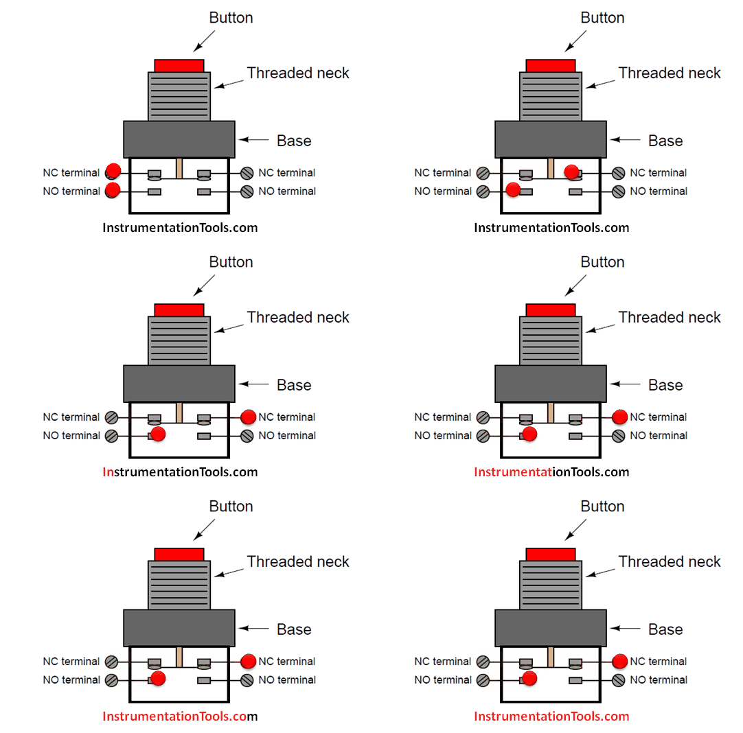
A common form of industrial push button switch looks something like this:

The threaded neck inserts through a hole cut into a metal or plastic panel, with a matching nut to hold it in place. Thus, the button faces the human operator(s) while the switch contacts reside on the other side of the panel.
When pressed, the downward motion of the actuator breaks the electrical bridge between the two NC contacts, forming a new bridge between the NO contacts:

The schematic diagram symbol for this type of switch looks much like the real thing, with the normally-closed contact set on top and the normally-open contact set below:

Connecting two of the terminals together makes this form of switch electrically identical to a Form C:

This switch contact arrangement is sometimes referred to as a form-C contact set, since it incorporates both a form-A contact (normally-open) as well as a form-B contact (normally-closed).
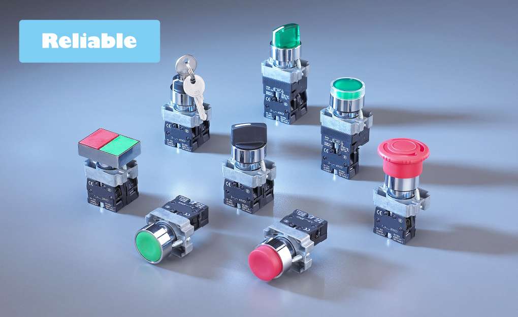
Most industrial hand switches are available in modular form, where sets of switch contact blocks may be “stacked” together to be actuated by the same pushbutton or rotary knob. This allows an almost unlimited number of switch contacts to be simultaneously actuated by a single actuating mechanism.
Different actuator types such as pushbuttons, rotary selectors, knobs, and key switches may also be interchanged with contact modules for maximum flexibility:

Switch Types
An electrical switch is any device used to interrupt the flow of electrons in a circuit. Switches are essentially binary devices: they are either completely on (“closed”) or completely off (“open”). There are many different types of switches, and we will explore some of these types in this chapter.
Though it may seem strange to cover this elementary electrical topic at such a late stage in this book series, I do so because the chapters that follow explore an older realm of digital technology based on mechanical switch contacts rather than solid-state gate circuits, and a thorough understanding of switch types is necessary for the undertaking.
Learning the function of switch-based circuits at the same time that you learn about solid-state logic gates makes both topics easier to grasp, and sets the stage for an enhanced learning experience in Boolean algebra, the mathematics behind digital logic circuits.
The simplest type of switch is one where two electrical conductors are brought in contact with each other by the motion of an actuating mechanism. Other switches are more complex, containing electronic circuits able to turn on or off depending on some physical stimulus (such as light or magnetic field) sensed.
In any case, the final output of any switch will be (at least) a pair of wire-connection terminals that will either be connected together by the switch’s internal contact mechanism (“closed”), or not connected together (“open”).
Any switch designed to be operated by a person is generally called a hand switch, and they are manufactured in several varieties:

Toggle switches are actuated by a lever angled in one of two or more positions. The common light switch used in household wiring is an example of a toggle switch.
Most toggle switches will come to rest in any of their lever positions, while others have an internal spring mechanism returning the lever to a certain normal position, allowing for what is called “momentary” operation.

Pushbutton switches are two-position devices actuated with a button that is pressed and released. Most pushbutton switches have an internal spring mechanism returning the button to its “out,” or “unpressed,” position, for momentary operation.
Some pushbutton switches will latch alternately on or off with every push of the button. Other pushbutton switches will stay in their “in,” or “pressed,” position until the button is pulled back out. This last type of pushbutton switches usually have a mushroom-shaped button for easy push-pull action.

Selector switches are actuated with a rotary knob or lever of some sort to select one of two or more positions.
Like the toggle switch, selector switches can either rest in any of their positions or contain spring-return mechanisms for momentary operation.

A joystick switch is actuated by a lever free to move in more than one axis of motion. One or more of several switch contact mechanisms are actuated depending on which way the lever is pushed, and sometimes by how far it is pushed. The circle-and-dot notation on the switch symbol represents the direction of joystick lever motion required to actuate the contact. Joystick hand switches are commonly used for crane and robot control.
Some switches are specifically designed to be operated by the motion of a machine rather than by the hand of a human operator. These motion-operated switches are commonly called limit switches, because they are often used to limit the motion of a machine by turning off the actuating power to a component if it moves too far. As with hand switches, limit switches come in several varieties:

These limit switches closely resemble rugged toggle or selector hand switches fitted with a lever pushed by the machine part.
Often, the levers are tipped with a small roller bearing, preventing the lever from being worn off by repeated contact with the machine part.

Proximity switches sense the approach of a metallic machine part either by a magnetic or high-frequency electromagnetic field. Simple proximity switches use a permanent magnet to actuate a sealed switch mechanism whenever the machine part gets close (typically 1 inch or less).
More complex proximity switches work like a metal detector, energizing a coil of wire with a high-frequency current, and electronically monitoring the magnitude of that current. If a metallic part (not necessarily magnetic) gets close enough to the coil, the current will increase, and trip the monitoring circuit.
The symbol shown here for the proximity switch is of the electronic variety, as indicated by the diamond-shaped box surrounding the switch. A non-electronic proximity switch would use the same symbol as the lever-actuated limit switch.
Another form of proximity switch is the optical switch, comprised of a light source and photocell. Machine position is detected by either the interruption or reflection of a light beam. Optical switches are also useful in safety applications, where beams of light can be used to detect personnel entry into a dangerous area.
In many industrial processes, it is necessary to monitor various physical quantities with switches. Such switches can be used to sound alarms, indicating that a process variable has exceeded normal parameters, or they can be used to shut down processes or equipment if those variables have reached dangerous or destructive levels. There are many different types of process switches:

These switches sense the rotary speed of a shaft either by a centrifugal weight mechanism mounted on the shaft, or by some kind of non-contact detection of shaft motion such as optical or magnetic.

Gas or liquid pressure can be used to actuate a switch mechanism if that pressure is applied to a piston, diaphragm, or bellows, which converts pressure to mechanical force.

An inexpensive temperature-sensing mechanism is the “bimetallic strip:” a thin strip of two metals, joined back-to-back, each metal having a different rate of thermal expansion. When the strip heats or cools, differing rates of thermal expansion between the two metals causes it to bend. The bending of the strip can then be used to actuate a switch contact mechanism.
Other temperature switches use a brass bulb filled with either a liquid or gas, with a tiny tube connecting the bulb to a pressure-sensing switch. As the bulb is heated, the gas or liquid expands, generating a pressure increase which then actuates the switch mechanism.

A floating object can be used to actuate a switch mechanism when the liquid level in an tank rises past a certain point. If the liquid is electrically conductive, the liquid itself can be used as a conductor to bridge between two metal probes inserted into the tank at the required depth.
The conductivity technique is usually implemented with a special design of relay triggered by a small amount of current through the conductive liquid. In most cases it is impractical and dangerous to switch the full load current of the circuit through a liquid.
Level switches can also be designed to detect the level of solid materials such as wood chips, grain, coal, or animal feed in a storage silo, bin, or hopper.
A common design for this application is a small paddle wheel, inserted into the bin at the desired height, which is slowly turned by a small electric motor. When the solid material fills the bin to that height, the material prevents the paddle wheel from turning. The torque response of the small motor than trips the switch mechanism.
Another design uses a “tuning fork” shaped metal prong, inserted into the bin from the outside at the desired height. The fork is vibrated at its resonant frequency by an electronic circuit and magnet/electromagnet coil assembly. When the bin fills to that height, the solid material dampens the vibration of the fork, the change in vibration amplitude and/or frequency detected by the electronic circuit.

Inserted into a pipe, a flow switch will detect any gas or liquid flow rate in excess of a certain threshold, usually with a small paddle or vane which is pushed by the flow.
Other flow switches are constructed as differential pressure switches, measuring the pressure drop across a restriction built into the pipe.

