
Rotary cam switches are widely used in industrial and electrical applications for controlling motors, circuits, and other electrical systems. Understanding the components of a rotary cam switch is essential for proper installation, maintenance, and troubleshooting.
Main Components of a Rotary Cam Switch
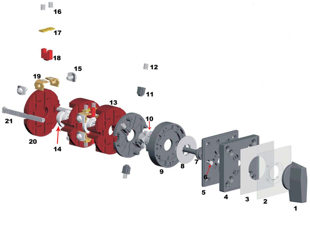
Below is a detailed breakdown of each element:
- Handle/Knob – The user-operated part used to change the switch position.
- Escutcheon plate / Face plate / Indicating Plate / Legend Plate – Decorative or informative plate indicating switch positions.
- Indicating Paper – A label visible through a transparent front plate for position identification.
- Plate Frame – Holds the face plate securely in place.
- Mounting Plate – Used for fixing the switch to a panel or enclosure.
- Holding Screw – Secures the mounting plate to the switch body.
- Shaft/Drive Shaft – Transmits rotational motion to the internal components.
- Limit Cam / Stopper – Limits the rotation to specific positions.
- Latching Mechanism – Keeps the switch in a set position until manually changed.
- Mech Cam – Controls the mechanical movement of the contacts.
- Mech Cam Follower – Follows the Mech Cam to actuate contact changes.
- Mech Cam Follower Spring – Returns the follower to its original position.
- Switching Cell/Chamber – Encloses the contact mechanism.
- Cam / Cam Wheel – Controls the timing and sequence of contact operations.
- Terminal Screw – Connects external wires to the switch.
- Cam Follower Spring – Ensures smooth contact movement.
- Moving Contacts – Open or close the circuit based on the cam position.
- Cam Follower – Follows the cam to actuate contact changes.
- Fixing Contacts – Stationary contact points.
- Bottom Plate – Provides structural support to the switch base.
- Side Rod/Bolt – Offers additional structural support or alignment.
Typical Applications of Rotary Cam Switches
- Motor Control: Used as motor switches for direct-on-line starting, reversing, and star-delta operations.
- Control Circuits: Applied in signaling, control, and measurement systems.
- Industrial Switching: Selector switches, step switches for transformers, welding equipment, resistors, and heaters.
- Automatic Return Switches: For applications requiring automatic reset after operation.
Design Features
- Up to 12 control positions and 12 switching elements (24 contacts) maximum.
- Available with turning angles of 30°, 45°, 60°, and 90°.
- Modular and customizable design for various industrial needs.
Suggested Additions to the Blog
- Illustrated Diagram – A labeled image of a rotary cam switch showing each component.
- Assembly Instructions – Step-by-step guide on how to assemble or disassemble the switch for maintenance.
- Comparison with Other Switch Types – How rotary cam switches differ from toggle switches, push-button switches, and electronic switches.
- Common Faults and Troubleshooting Tips – Guide on identifying and resolving common issues.
- Real-World Use Cases – Examples of how rotary cam switches are used in automation, machinery, and control panels.